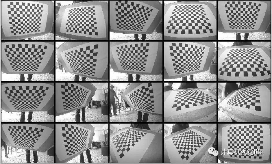
triangulation
tip: e2 (the epipole of the second image is the projection of the first image’s focal point (camera centre) into the second camera’s coordinate system), e2 = K’[R T][0,0,0,1]T ([0,0,0,1] is the coordinate origin of the first image (the origin of the world coordinate system))
Question 1: Why do we need camera calibration?
The purpose of camera calibration is to build a geometric model of camera imaging and to correct lens distortion. That sentence is a bit of a mouthful, so its two key parts are explained separately below.
Building the geometric model of camera imaging: the primary task of computer vision is to recover information about objects in the real 3D world from captured images. It is therefore essential to build a geometric model of how objects are mapped from the 3D world onto the camera’s imaging plane, and the most critical part of this is obtaining the camera’s intrinsic and extrinsic parameters (explained in detail later).
Correcting lens distortion: the first thing we learn about imaging is probably the pinhole camera. However, because light can only pass through the tiny hole, the image is very dim, so clever humans invented the lens. That solved the brightness problem, but introduced a new one: owing to the lens manufacturing process, the image suffers from various forms of distortion. To remove the distortion (so that the captured image matches the real-world scene), people compute distortion coefficients and use them to correct these aberrations. Although it is theoretically possible to design lenses that produce no distortion, they are much more complicated to manufacture than spherical lenses, so rather than a complex and costly manufacturing process, people prefer to solve the problem with mathematics.
Camera imaging model
As mentioned above, one goal of camera calibration is to establish the correspondence between objects in the 3D world and the coordinate points on the imaging plane, so we first need to define the following coordinate systems to lay the groundwork for the whole process:
World coordinate system: a user-defined coordinate system of the 3D world, introduced to describe the position of the target object in the real world. Unit: m.
Camera coordinate system: a coordinate system attached to the camera, defined to describe object positions from the camera’s point of view; it is the intermediate link between the world coordinate system and the image/pixel coordinate systems. Unit: m.
Image coordinate system: introduced to describe the perspective projection of objects from the camera coordinate system to the image coordinate system during imaging, which makes it easy to then obtain coordinates in the pixel coordinate system. Unit: m.
Pixel coordinate system: introduced to describe the coordinates of image points on the digital image (photo) after imaging; it is the coordinate system of the information we actually read out of the camera. Unit: pixels (count).
Defining four coordinate systems at once may be a little confusing; the figure below shows the relationships between them more clearly: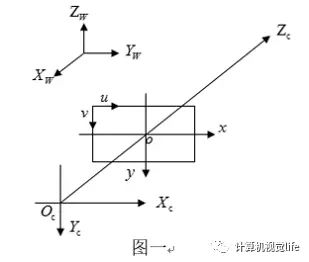
World coordinate system: Xw, Yw, Zw. Camera coordinate system: Xc, Yc, Zc. Image coordinate system: x, y. Pixel coordinate system: u, v.
Here, the z-axis of the camera coordinate system coincides with the optical axis, is perpendicular to the image plane and passes through the origin of the image coordinate system; the distance between the camera coordinate system and the image coordinate system is the focal length f (i.e. the origin of the image coordinate system coincides with the focal point). The pixel plane u-v coincides with the image plane x-y, but the origin of the pixel coordinate system is at the top-left corner of the image (defined this way so that reading and writing start from the first address of the stored data).
Next, we apply a series of transformations to the rigid body: an affine transformation from the world coordinate system, then perspective projection, finally obtaining discrete image points in the pixel coordinate system, introducing each parameter matrix step by step along the way.